This post is also being discussed on Hacker News!
The Paywall of PCI-E Bifurcation
PCI-E provides CPUs the ability to connect with fast devices, like >10 Gbps networks, NVMe SSD, etc. Especially for the usage of workstations or servers, the number PCI-E slots means a lot. As a result, Xeon CPUs and server-level MBs provide more PCI-E slots than on the consumer level. On the other hand, the number of PCI-E slots on cheap MB is usually only 1 for GPU. However, those server-level MBs are more expensive.
PCI-E bifurcation is a method of dividing x16 PCI-E channels into various combinations, such as 8+8 or 8+4+4. This approach is useful for devices that only support x4 or x8 speeds. However, unlike AMD, Intel's consumer-level motherboards seldom provide this option in the BIOS, especially on lower-end products.
Note: PLX chips can also function as switches to achieve similar results but are costly.
Bypass the paywall
Let's do some hacking to bypass such paywall. My platform is Intel Core i5-3450 + Z77, but I guess this method is also useful for any Intel CPU with public datasheet information, like 12th gen CPU[3].
First, go to the Intel ark document webpage to check the "PCI Express Configurations", which will show all bifurcation modes that your CPU supports.
For my CPU, 16=8+8=8+4+4, which provides the opportunity to place one x8 HBA card and 2 x4 NVMe SSD in one PCI-E slot!

Second, get the datasheet of your CPU, and search for bifurcation-related content. You will find the config (CFG) to control PCI-E bifurcation.
the datasheet contains infos like the definitions of LGA1155, so that we can control it manaully.
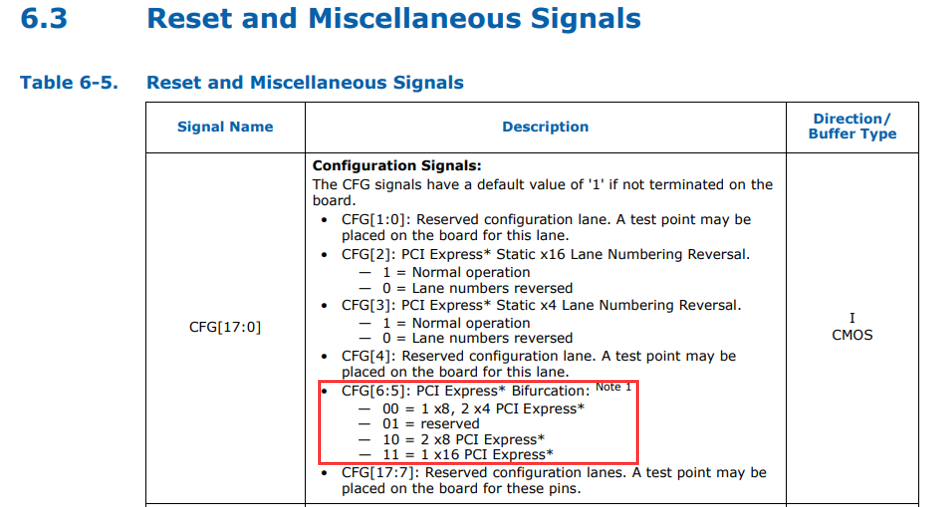
As the fig above, the value of CFG[6:5] controls bifurcation modes on my platform, and:
- 00: 8+4+4
- 10: 8+8
- 11: 16
note: CFG[17:0] means 18 pins of LGA1155.
And then we search the positions of CFG pins to hard-set their values as we wish.
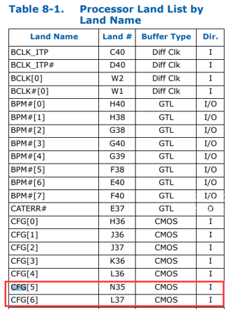
It shows that CFG[5] is N35, and CFG[6] is L37. So that we can find the actual physical position of CFG[5] and CFG[6].
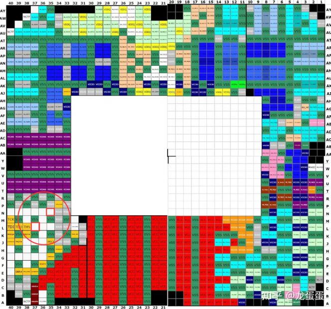
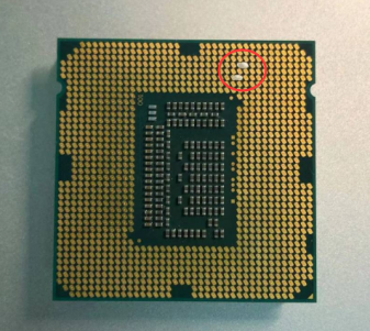
As mentioned above, I want to set 16=8+4+4, so the values of CFG[5] and CFG[6] should be both 0. So we can ground CFG[5] and CFG[6] by connecting N35<->M35 and L37<->M37. (VSS is GND, and VCC is PWR)
I used some silver paste to make such hard strap.
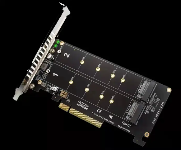
Last, get a cheap PCI-E bifurcation card with clock MUX, like multiple NVMe SSDs in one PCIE card.
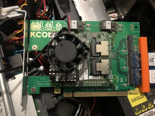
On my config, there is one LSI 2308 (OCP) with 2 NVMe Optane M10 in one PCI-E card. (buff叠满
 1
1
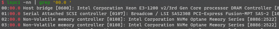
Now you can enjoy multiple devices with fast connections!
Small modification, big impact. So why MB producers disable this feature?
- I tried to use AMIBCP/UEFI tools to modify potentially hidden options in BIOS firmware, but sadly found nothing
FYI:
- You can also split the PCI-E lanes of PCH by modifying the BIOS firmware, but this process is more complex. But this is also a stable hacking method.
ref
- https://zhuanlan.zhihu.com/p/70125574
- https://www.bilibili.com/read/cv15596863/
- https://www.bilibili.com/read/cv16530665/